Multiplexer
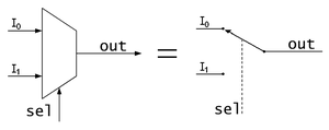
Schematic of a 2-to-1 Multiplexer. It can be equated to a controlled switch.

Schematic of a 1-to-2 Demultiplexer. Like a multiplexer, it can be equated to a controlled switch.
In electronics, a multiplexer (or mux) is a device that combines several analog or digital input signals and forwards them into a single output line.[1] A multiplexer of 2n{displaystyle 2^{n}}

An electronic multiplexer makes it possible for several signals to share one device or resource, for example, one A/D converter or one communication line, instead of having one device per input signal.
Conversely, a demultiplexer (or demux) is a device taking a single input signal and selecting one of many data-output-lines, which is connected to the single input. A multiplexer is often used with a complementary demultiplexer on the receiving end.[1]
An electronic multiplexer can be considered as a multiple-input, single-output switch, and a demultiplexer as a single-input, multiple-output switch.[3] The schematic symbol for a multiplexer is an isosceles trapezoid with the longer parallel side containing the input pins and the short parallel side containing the output pin.[4] The schematic on the right shows a 2-to-1 multiplexer on the left and an equivalent switch on the right. The sel{displaystyle sel}
Contents
1 Cost saving
2 Digital multiplexers
2.1 Chaining multiplexers
2.2 List of ICs which provide multiplexing
3 Digital demultiplexers
3.1 List of ICs which provide demultiplexing
4 Multiplexers as PLDs
5 See also
6 References
7 Further reading
8 External links
Cost saving
The basic function of a multiplexer: combining multiple inputs into a single data stream. On the receiving side, a demultiplexer splits the single data stream into the original multiple signals.
One use for multiplexers is economizing connections over a single channel, by connecting the multiplexer's single output to the demultiplexer's single input.
The image to the right demonstrates this benefit.
In this case, the cost of implementing separate channels for each data source is higher than the cost and inconvenience of providing the multiplexing/demultiplexing functions.
At the receiving end of the data link a complementary demultiplexer is usually required to break the single data stream back down into the original streams.
In some cases, the far end system may have functionality greater than a simple demultiplexer; and while the demultiplexing still occurs technically, it may never be implemented discretely.
This would be typical when: a multiplexer serves a number of IP network users; and then feeds directly into a router, which immediately reads the content of the entire link into its routing processor; and then does the demultiplexing in memory from where it will be converted directly into IP sections.
Often, a multiplexer and demultiplexer are combined together into a single piece of equipment, which is conveniently referred to as a "multiplexer". Both circuit elements are needed at both ends of a transmission link because most communications systems transmit in both directions.
In analog circuit design, a multiplexer is a special type of analog switch that connects one signal selected from several inputs to a single output.
Digital multiplexers
In digital circuit design, the selector wires are of digital value. In the case of a 2-to-1 multiplexer, a logic value of 0 would connect I0{displaystyle scriptstyle I_{0}}

In larger multiplexers, the number of selector pins is equal to ⌈log2(n)⌉{displaystyle scriptstyle leftlceil log _{2}(n)rightrceil }

For example, 9 to 16 inputs would require no fewer than 4 selector pins and 17 to 32 inputs would require no fewer than 5 selector pins. The binary value expressed on these selector pins determines the selected input pin.
A 2-to-1 multiplexer has a boolean equation where A{displaystyle scriptstyle A}


- Z=(A⋅S¯)+(B⋅S){displaystyle Z=(Acdot {overline {S}})+(Bcdot S)}

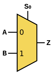
A 2-to-1 mux
Which can be expressed as a truth table:
| S{displaystyle scriptstyle S} | A{displaystyle scriptstyle A} | B{displaystyle scriptstyle B} | Z{displaystyle scriptstyle Z} |
|---|---|---|---|
| 0 | 0 | 0 | 0 |
| 0 | 0 | 1 | 0 |
| 0 | 1 | 0 | 1 |
| 0 | 1 | 1 | 1 |
| 1 | 0 | 0 | 0 |
| 1 | 0 | 1 | 1 |
| 1 | 1 | 0 | 0 |
| 1 | 1 | 1 | 1 |
Or, in simpler notation:
| S{displaystyle scriptstyle S} | Z{displaystyle scriptstyle Z} |
|---|---|
| 0 | A |
| 1 | B |
These tables show that when S=0{displaystyle scriptstyle S=0}


Larger multiplexers are also common and, as stated above, require ⌈log2(n)⌉{displaystyle scriptstyle leftlceil log _{2}(n)rightrceil }

4-to-1 mux
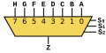
8-to-1 mux

16-to-1 mux


The boolean equation for a 4-to-1 multiplexer is:
- Z=(A⋅S0¯⋅S1¯)+(B⋅S0⋅S1¯)+(C⋅S0¯⋅S1)+(D⋅S0⋅S1){displaystyle Z=(Acdot {overline {S_{0}}}cdot {overline {S_{1}}})+(Bcdot S_{0}cdot {overline {S_{1}}})+(Ccdot {overline {S_{0}}}cdot S_{1})+(Dcdot S_{0}cdot S_{1})}

The following 4-to-1 multiplexer is constructed from 3-state buffers and AND gates (the AND gates are acting as the decoder):
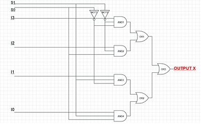
A 4:1 MUX circuit using 3 input AND and other gates

The subscripts on the In{displaystyle scriptstyle I_{n}}
Chaining multiplexers
Larger Multiplexers can be constructed by using smaller multiplexers by chaining them together. For example, an 8-to-1 multiplexer can be made with two 4-to-1 and one 2-to-1 multiplexers. The two 4-to-1 multiplexer outputs are fed into the 2-to-1 with the selector pins on the 4-to-1's put in parallel giving a total number of selector inputs to 3, which is equivalent to an 8-to-1.
List of ICs which provide multiplexing

Signetics S54S157
The 7400 series has several ICs that contain multiplexer(s):
| IC No. | Function | Output State |
|---|---|---|
| 74157 | Quad 2:1 mux. | Output same as input given |
| 74158 | Quad 2:1 mux. | Output is inverted input |
| 74153 | Dual 4:1 mux. | Output same as input |
| 74352 | Dual 4:1 mux. | Output is inverted input |
| 74151A | 8:1 mux. | Both outputs available (i.e., complementary outputs) |
| 74151 | 8:1 mux. | Output is inverted input |
| 74150 | 16:1 mux. | Output is inverted input |
Digital demultiplexers
Demultiplexers take one data input and a number of selection inputs, and they have several outputs.
They forward the data input to one of the outputs depending on the values of the selection inputs.
Demultiplexers are sometimes convenient for designing general purpose logic, because if the demultiplexer's input is always true, the demultiplexer acts as a decoder.
This means that any function of the selection bits can be constructed by logically OR-ing the correct set of outputs.
If X is the input and S is the selector, and A and B are the outputs:
A=(X⋅S¯){displaystyle A=(Xcdot {overline {S}})}

B=(X⋅S){displaystyle B=(Xcdot S)}

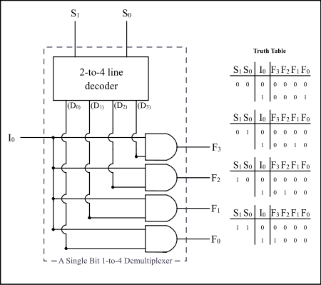
Example: A Single Bit 1-to-4 Line Demultiplexer
List of ICs which provide demultiplexing

Fairchild 74F138
The 7400 series has several ICs that contain demultiplexer(s):
| IC No. (7400) | IC No. (4000) | Function | Output State |
|---|---|---|---|
| 74139 | Dual 1:4 demux. | Output is inverted input | |
| 74156 | Dual 1:4 demux. | Output is open collector | |
| 74138 | 1:8 demux. | Output is inverted input | |
| 74238 | 1:8 demux. | ||
| 74154 | 1:16 demux. | Output is inverted input | |
| 74159 | CD4514/15 | 1:16 demux. | Output is open collector and same as input |
Multiplexers as PLDs
Multiplexers can also be used as programmable logic devices, specifically to implement Boolean functions. Any Boolean function of n variables and one result can be implemented with a multiplexer with n selector inputs. The variables are connected to the selector inputs, and the function result, 0 or 1, for each possible combination of selector inputs is connected to the corresponding data input. This is especially useful in situations when cost is a factor, for modularity, and for ease of modification. If one of the variables (for example, D) is also available inverted, a multiplexer with n-1 selector inputs is sufficient; the data inputs are connected to 0, 1, D, or ~D, according to the desired output for each combination of the selector inputs.[6]
See also
Digital subscriber line access multiplexer (DSLAM)- Inverse multiplexer
Multiplexing
- Code-division multiplexing
- Frequency-division multiplexing
- Time-division multiplexing
- Wavelength-division multiplexing
- Statistical multiplexing
- Charlieplexing
- Priority encoder
Rule 184, a cellular automaton in which each cell acts as a multiplexer for the values from the two adjacent cells- Statistical multiplexer
References
^ abc Dean, Tamara (2010). Network+ Guide to Networks. Delmar. pp. 82–85..mw-parser-output cite.citation{font-style:inherit}.mw-parser-output .citation q{quotes:"""""""'""'"}.mw-parser-output .citation .cs1-lock-free a{background:url("//upload.wikimedia.org/wikipedia/commons/thumb/6/65/Lock-green.svg/9px-Lock-green.svg.png")no-repeat;background-position:right .1em center}.mw-parser-output .citation .cs1-lock-limited a,.mw-parser-output .citation .cs1-lock-registration a{background:url("//upload.wikimedia.org/wikipedia/commons/thumb/d/d6/Lock-gray-alt-2.svg/9px-Lock-gray-alt-2.svg.png")no-repeat;background-position:right .1em center}.mw-parser-output .citation .cs1-lock-subscription a{background:url("//upload.wikimedia.org/wikipedia/commons/thumb/a/aa/Lock-red-alt-2.svg/9px-Lock-red-alt-2.svg.png")no-repeat;background-position:right .1em center}.mw-parser-output .cs1-subscription,.mw-parser-output .cs1-registration{color:#555}.mw-parser-output .cs1-subscription span,.mw-parser-output .cs1-registration span{border-bottom:1px dotted;cursor:help}.mw-parser-output .cs1-ws-icon a{background:url("//upload.wikimedia.org/wikipedia/commons/thumb/4/4c/Wikisource-logo.svg/12px-Wikisource-logo.svg.png")no-repeat;background-position:right .1em center}.mw-parser-output code.cs1-code{color:inherit;background:inherit;border:inherit;padding:inherit}.mw-parser-output .cs1-hidden-error{display:none;font-size:100%}.mw-parser-output .cs1-visible-error{font-size:100%}.mw-parser-output .cs1-maint{display:none;color:#33aa33;margin-left:0.3em}.mw-parser-output .cs1-subscription,.mw-parser-output .cs1-registration,.mw-parser-output .cs1-format{font-size:95%}.mw-parser-output .cs1-kern-left,.mw-parser-output .cs1-kern-wl-left{padding-left:0.2em}.mw-parser-output .cs1-kern-right,.mw-parser-output .cs1-kern-wl-right{padding-right:0.2em}
^ Debashis, De (2010). Basic Electronics. Dorling Kindersley. p. 557.
^ Lipták, Béla (2002). Instrument engineers' handbook: Process software and digital networks. CRC Press. p. 343.
^ Harris, David (2007). Digital Design and Computer Architecture. Penrose. p. 79.
^ Crowe, John and Barrie Hayes-Gill (1998) Introduction to Digital Electronics pp. 111-113
^ Donald E. Lancaster (1975). The TTL Cookbook. Howard W. Sams & Co. pp. 140–143.
Further reading
M. Morris Mano; Charles R. Kime (2008). Logic and Computer Design Fundamentals (4 ed.). Prentice Hall. ISBN 0-13-198926-X.
External links
 The dictionary definition of multiplexer at Wiktionary
 Media related to Multiplexers at Wikimedia Commons
Authority control |
|
|---|


